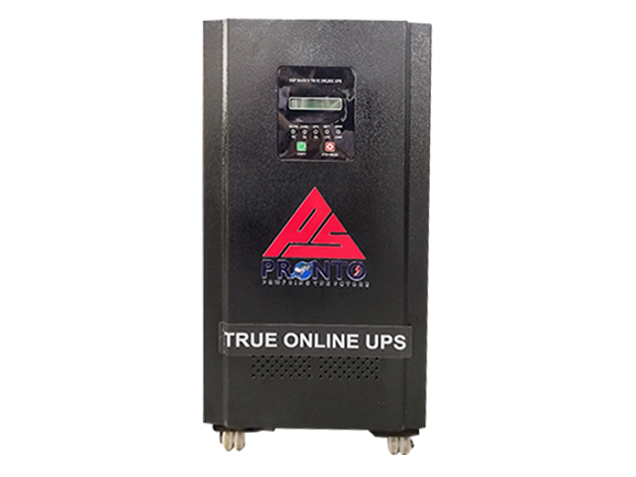
3P-1P OLU (5KVA - 40KVA)
Our USP
- Pure Sine Wave Output
- Bypass Facility
- SCR/IGBT (PFC) Based Charger
- User Configurable Parameter
- Inverter Isolation Transformer
PRONTO RENEWABLES ENERGY PVT LTD | ||||||||
| PRONTO ONLINE UPS (3P-1P) - SPECIFICATIONS | ||||||||
| Models | Prime TS (For PFC) & SUPREME TS (For SCR) | |||||||
| Ratings | 5KVA | 10KVA | 15KVA | 20KVA | 25KVA | 30KVA | 40KVA | |
| 1 | Operating DC Voltage (For PFC) | 240V - 360V | 240V - 360V | 240V - 360V | 240V - 360V | - | - | - |
| 2 | No. Of Batteries (For PFC) | 20 - 30 | 20 - 30 | 20 - 30 | 20 - 30 | - | - | - |
| 3 | Operation DC Voltage (For SCR) | 324V - 360V | 324V -360V | 360V | 360V | 324V - 360V | 324V - 360V | 360V |
| 4 | No. Of Batteries (For SCR) | 27 - 30 | 27- 30 | 30 | 30 | 27 - 30 | 27 - 30 | 30 |
| A | MAINS MODE | |||||||
| 1 | No. of Phase | 3 Phase - 4 Wire R, Y, B, N | ||||||
| 2 | Voltage Range | 340V - 480V AC | ||||||
| 3 | Input Power Factor (For PFC) | 0.9 | ||||||
| 4 | Input Power Factor (For SCR) | 0.8 | ||||||
| 5 | Input THD | Less than 3% | ||||||
| 6 | Frequency Range (For PFC) | 40 - 60 Hz | ||||||
| 7 | Frequency Range (For SCR) | 47 - 53 Hz | ||||||
| B | INVERTER MODE | |||||||
| 1 | Switching Power Device | IGBT MODULES | ||||||
| 2 | Control | DSP Based PWM | ||||||
| 3 | Output Voltage | 230V AC +/- 1% | ||||||
| 4 | Phase | 1 Phase - 3 wire P, N, E | ||||||
| 5 | Output Waveform | Pure Sine Wave | ||||||
| 6 | Frequency | 50 Hz (Free running) | ||||||
| 7 | Changeover Time | Zero second | ||||||
| 8 | Rated Output Power Factor | 0.8 | ||||||
| 9 | Load Capacity | 100 % Continuous | ||||||
| 10 | Overload | 110 % for 20 Second, 150% Instant trip | ||||||
| 11 | THD | Less than 2% On linear load and Less than 5% on non linear laod | ||||||
| 12 | Transient Response | On 100% step laod change output stays within 5% and recovers within half cycle | ||||||
| 13 | Crest Factor | 3 : 1 | ||||||
| 14 | Switch | UPS START, STOP/RESET | ||||||
| 15 | LCD Display Parameters | Input Voltage, Output Voltage, Output Frequency, Output Current, Batttery Voltage, Charging Current | ||||||
| 16 | LED Indiaction | Mains ON, Charging ON, UPS ON. Low Batttery, Overload | ||||||
| 17 | Alarm | Batterty Low, Overlaod, Charger ON | ||||||
| 18 | Protection | Overload, Short Circuit, O/V, Mains Surge,U/V and O/V Protection | ||||||
| 19 | Bypass | Manual Bypass, Static Bypass (Optional) | ||||||
| 20 | Operating Temp | 0-50°C | ||||||
| 21 | Operating Humidity (RH Value) | Less than 95 | ||||||
| 22 | Protection Class | IP 20 | ||||||
| 23 | Low Cut Off | 10.5V/Batt.+/-2% | ||||||
| 24 | Battery Low Buzzer | 10.75V/ Batt. +/-2% | ||||||
| 25 | Low Cut off Recovery | 12V/ Batt. +/-2% | ||||||
| 26 | Charging Current | 10% of Battery AH | ||||||
| 27 | Communication | RS485 (Optional) | ||||||
| C | Dimensions (In mm) | 5KVA | 10KVA | 15KVA | 20KVA | 25KVA | 30KVA | 40KVA |
| 1 | For PFC (W×D×H) | 370×725×790 | 4700×810×900 | - | - | - | ||
| 2 | For SCR (W×D×H) | 370×725×790 | 470×810×900 | 470×1090×900 | ||||
| Note:The specifications & Design are subject to change due to continuous improvements. | ||||||||

